
Chapter 9 discussed a number of calculations that can be performed on a single primitive. Here, we present a number of useful calculations that operate on more than one primitive. This appendix is a collection of various geometric calculations that are sometimes useful. It is also instructive to browse these tests, because many illustrate general principles.
A more comprehensive list of fast intersection methods can be found at http://www.realtimerendering.com/intersections.html.
A.1Closest Point on 2D Implicit Line
Consider an infinite line
where
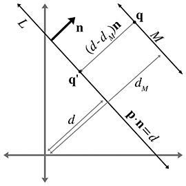
Let
Now the signed distance from
This distance is obviously the same as the distance from
A.2Closest Point on a Parametric Ray
Consider the parametric ray
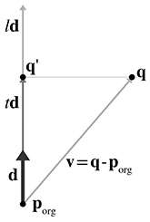
where
This is just a simple matter of projecting one vector onto another, which was presented in
Section 2.11.2. Let
The value of the dot product
Actually, Equation (A.2), for
If the ray is defined where
A.3Closest Point on a Plane
Consider a plane
where
We showed how to compute the distance from a point to a plane in
Section 9.5.4. To compute
Notice that this is the same as Equation (A.1), which computes the closest point to an implicit line in 2D.
A.4Closest Point on a Circle or Sphere
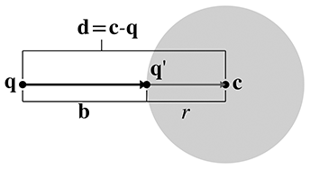
Imagine a 2D point
Let
Now, clearly,
Adding this displacement to
If
A.5Closest Point in an AABB
Let
if (x < minX) {
    x = minX;
} else if (x > maxX) {
    x = maxX;
}

if (y < minY) {
    y = minY;
} else if (y > maxY) {
    y = maxY;
}

if (z < minZ) {
    z = minZ;
} else if (z > maxZ) {
    z = maxZ;
}
A.6Intersection Tests
The remaining sections of this chapter present an assortment of intersection tests. These tests are designed to determine whether two geometric primitives intersect, and (in some cases) to locate the intersection. We will consider different two types of intersection tests: static and dynamic.
- A static test checks two stationary primitives and detects whether the two primitives intersect. It is a Boolean test—that is, it usually returns only true (there is an intersection) or false (there is no intersection). If the test returns more details about the intersection, this extra information usually has the purpose of describing where the intersection occurred.
-
A dynamic test checks two moving primitives and
detects if and when two primitives intersect. Usually, the movement
is expressed parametrically, and therefore the result of such a
test is not only a Boolean true/false result but also a time value
(the value of the parameter
Although each object may have its own displacement over the time interval under consideration, it will be often easier to view the problem from the point of view of one of the primitives, considering that primitive to be “still” while the other primitive does all of the “moving.” We can easily do this by combining the two displacement vectors to get a single relative displacement vector that describes how the two primitives move in relation to each other. Thus, the dynamic tests will usually involve one stationary primitive and one moving primitive.
Notice that many important tests involving rays are actually dynamic tests, since a ray can be viewed as a moving point.
A.7Intersection of Two Implicit Lines in 2D
Finding the intersection of two lines defined implicitly in 2D is a straightforward matter of
solving a system of linear equations. We have two equations (the two implicit equations of the
lines) and two unknowns (the
Solving this system of equations yields
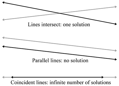
Computing the intersection of two lines in 2DJust as for any system of linear equations, there are three solution possibilities (as illustrated in Figure A.4):
- There is one solution. In this case, the denominators in Equation (A.3) will be nonzero.
- There are no solutions. This indicates that the lines are parallel and not intersecting. The denominators are zero.
- There are an infinite number of solutions. This is the case when the two lines are coincident. All the numerators and denominators are zero in this case.
A.8Intersection of Two Rays in 3D
Given two rays in 3D defined parametrically by
we can solve for their point of intersection. For a moment, let us not restrict the range of
- The rays intersect at exactly one point.
- The rays are parallel, and there is no intersection.
- The rays are coincident, and there are an infinite number of solutions
However, in 3D we have a fourth case, where the rays are skew and do not share a common plane. An example of skew lines is illustrated in Figure A.5.
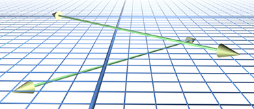
We can solve for
We obtain
If the lines are parallel (or coincident), then the cross product of
This discussion has assumed that the range of the parameters
A.9Intersection of a Ray and Plane
A ray intersects a plane in 3D at a point. Let the ray be defined parametrically by
The plane will be defined in the standard implicit manner, by all points
Although we often restrict the plane normal
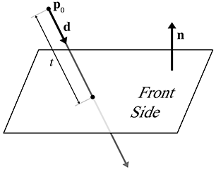
Let us solve for
If the ray is parallel to the plane, then the denominator
A.10Intersection of an AABB and Plane
Consider a 3D axially aligned bounding box defined by extreme points
where
One obvious implementation strategy for a static test would be to classify each corner point as
being on either the front or back side of the plane. We do this by taking the dot products of
the corner points with
As it turns out, we don't have to check all eight corner points. We'll use a trick similar to the
one used in Section 9.4.4 to transform an AABB. For example, if
// Perform static AABB-plane intersection test.  Returns:
//
// <0   Box is completely on the BACK side of the plane
// >0   Box is completely on the FRONT side of the plane
// 0    Box intersects the plane
int AABB3::classifyPlane(const Vector3 &n, float d) const {

    // Inspect the normal and compute the minimum and maximum
    // D values.
    float minD, maxD;

    if (n.x > 0.0f) {
        minD = n.x*min.x; maxD = n.x*max.x;
    } else {
        minD = n.x*max.x; maxD = n.x*min.x;
    }

    if (n.y > 0.0f) {
        minD += n.y*min.y; maxD += n.y*max.y;
    } else {
        minD += n.y*max.y; maxD += n.y*min.y;
    }

    if (n.z > 0.0f) {
        minD += n.z*min.z; maxD += n.z*max.z;
    } else {
        minD += n.z*max.z; maxD += n.z*min.z;
    }

    // Check if completely on the front side of the plane
    if (minD >= d) {
        return +1;
    }

    // Check if completely on the back side of the plane
    if (maxD <= d) {
        return -1;
    }

    // We straddle the plane
    return 0;
}
A dynamic test is just one step further. Let's consider the plane to be stationary (recall from
Section A.6 that it is simpler to view the test from the frame of reference
of one of the moving objects). The displacement of the box will be defined by a unit vector
A.11Intersection of Three Planes
In 3D, three planes intersect at a point, as shown in Figure A.7.
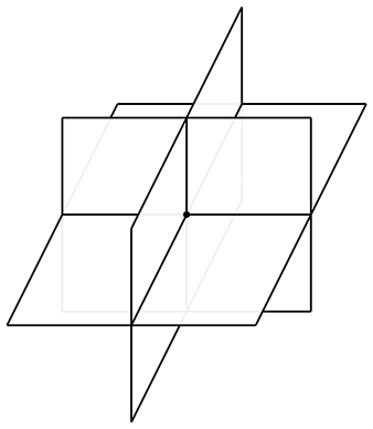
Let the three planes be defined implicitly as
Although we usually use unit vectors for the plane normals, in this case it is not necessary that
If any pair of planes is parallel, then the point of intersection either does not exist or is not unique. In either case, the triple product in the denominator is zero.
A.12Intersection of Ray and a Circle or Sphere
This section discusses how to compute the intersection of a ray and a circle in 2D. This also works for computing the intersection of a ray and a sphere in 3D, since we can operate in the plane that contains the ray and the center of the circle and turn the 3D problem into a 2D one. (If the ray lies on a line that passes through the center of the sphere, the plane is not uniquely defined. This not a problem, however, because any of the infinitely many planes that pass through the ray and the center of the sphere can be used.)
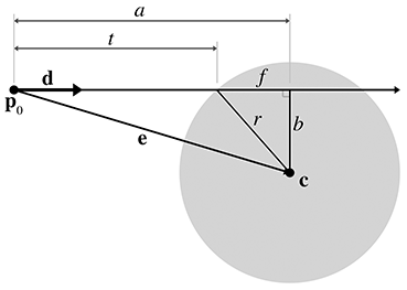
We will use a construction inspired by Hultquist [5]; see
Figure A.8. The sphere is defined by its center
In this case, we use a unit vector
We are solving for the value of
Now we project
Now all that remains is to compute
We can solve for
where
Substituting and solving for
Finally, solving for
If the argument to the square root (
The origin of the ray could be inside the sphere. This is indicated by
A.13Intersection of Two Circles or Spheres
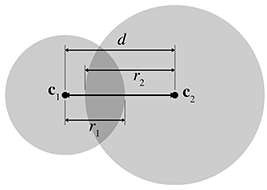
Detecting the static intersection of two spheres is relatively easy. (The discussion in this
section also applies to circles—in fact, we use circles in the diagrams.) Consider two spheres
defined by centers
Detecting the intersection of two moving spheres is slightly more difficult. Assume, for the
moment, that we have two separate displacement vectors
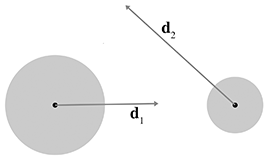
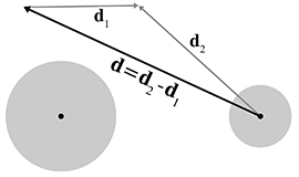
We can simplify the problem by viewing it from the point of view of the first sphere, considering
that sphere to be “stationary” while the other sphere is the “moving” sphere. This gives us
a single displacement vector
Let the stationary sphere be defined by its center
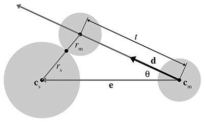
To solve for
According to the law of cosines (see Section 1.4.5), we have
Which root do we pick? The lower number (the negative root) produces the
If
A.14Intersection of a Sphere and AABB
To detect the static intersection of a sphere and an AABB, we first find the point on the box that is closest to the center of the sphere by using the techniques from Section A.5. We compute the distance from this point to the center of the sphere and compare this distance with the radius. (Actually, in practice we compare the distance squared against the radius squared to avoid the square root in the distance computation.) If the distance is smaller than the radius, then the sphere intersects the AABB.
Arvo [1] discusses this technique, which he uses for intersecting spheres with “solid” boxes. He also discusses some tricks for intersecting spheres with “hollow” boxes.
Unfortunately, the dynamic test is more complicated than the static one. For details, see Lengyel [6].
A.15Intersection of a Sphere and a Plane
Detecting the static intersection of a sphere and a plane is relatively easy—we simply compute the distance from the center of the sphere to the plane by using Equation (9.14). If this distance is less than the radius of the sphere, then the sphere intersects the plane. We can actually make a more robust test, which classifies the sphere as being completely on the front, completely on the back, or straddling the sphere. A code snippet is given in Listing A.3.
// Given a sphere and plane, determine which side of the plane
// the sphere is on.
//
// Return values:
//
// < 0  Sphere is completely on the back
// > 0  Sphere is completely on the front
// 0    Sphere straddles plane

int classifySpherePlane(
    const Vector3 &planeNormal,  // must be normalized
    float          planeD,       // p * planeNormal = planeD
    const Vector3 &sphereCenter, // center of sphere
    float          sphereRadius  // radius of sphere
) {

    // Compute distance from center of sphere to the plane
    float d = planeNormal * sphereCenter - planeD;

    // Completely on the front side?
    if (d >= sphereRadius) {
        return +1;
    }

    // Completely on the back side?
    if (d <= -sphereRadius) {
        return -1;
    }

    // Sphere intersects the plane
    return 0;
}
The dynamic situation is only slightly more complicated. We consider the plane to be stationary, assigning all relative displacement to the sphere.
We define the plane in the usual manner by a normalized surface normal
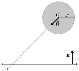
The problem is greatly simplified by realizing that no matter where on the surface of the plane
the intersection occurs, the point of contact on the surface of the sphere is always the same.
That point of contact
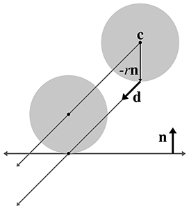
Now that we know which point on the sphere first contacts the plane, we can use a simple
ray-plane intersection test from Section A.9. We start with our solution
to the ray-plane intersection test from Equation (A.4) and then substitute
A.16Intersection of a Ray and a Triangle
The ray-triangle intersection test is very important in graphics and computational geometry. In the absence of a special raytrace test against a given complex object, we can always represent (or at least approximate) the surface of an object as a triangle mesh and then raytrace against this triangle mesh representation.
Here we use a simple strategy from Badouel [2]. The first step is to compute the point where the ray intersects the plane containing the triangle. Section A.9 showed how to compute the intersection of a plane and a ray. Then we test to see whether that point is inside the triangle by computing the barycentric coordinates of the point, as discussed in Section 9.6.4.
To speed up this test, we use a few tricks:
- Detect and return a negative result (no collision) as soon as possible. This is known as “early out.”
- Defer expensive mathematical operations, such as division, as long as possible. This is done for two reasons. First, if the result of the expensive calculation is not needed (for example, if we took an early out), then the time we spent performing the operation was wasted. Second, it gives the compiler plenty of room to take advantage of the operator pipeline in modern processors. If an operation such as division has a long latency, then the compiler may be able to look ahead and generate code that begins the division operation early. It then generates code that performs other tests (possibly taking an early out) while the division operation is under way. Then, at execution time, if and when the result of the division is actually needed, the result will be available or at least partially completed.
- Only detect collisions where the ray approaches the triangle from the front side. This allows us to take a very early out on approximately half of the triangles. Intersecting with both sides is slightly slower.
Listing A.4 implements these techniques. Although it is commented in the listing, we have chosen to perform some floating point comparisons “backwards” since this behaves better in the presence of invalid floating point input data and NaNs (Not a Number).
float rayTriangleIntersect(
    const Vector3 &rayOrg,   // origin of the ray
    const Vector3 &rayDelta, // ray length and direction
    const Vector3 &p0,       // triangle vertices
    const Vector3 &p1,       // .
    const Vector3 &p2,       // .
    float minT               // closest intersection found so far.
                             // (Start with 1.0)
) {

    // We'll return this huge number of no intersection is detected
    const float kNoIntersection = FLT_MAX;

    // Compute clockwise edge vectors.
    Vector3 e1 = p1 - p0;
    Vector3 e2 = p2 - p1;

    // Compute surface normal.  (Unnormalized)
    Vector3 n = crossProduct(e1, e2);

    // Compute gradient, which tells us how steep of an angle
    // we are approaching the *front* side of the triangle
    float dot = n * rayDelta;

    // Check for a ray that is parallel to the triangle, or not
    // pointing towards the front face of the triangle.
    //
    // Note that this also will reject degenerate triangles and
    // rays as well.  We code this in a very particular
    // way so that NANs will bail here.  (I.e. this does NOT
    // behave the same as ``dot >= 0.0f'' when NANs are involved)
    if (!(dot < 0.0f)) {
        return kNoIntersection;
    }

    // Compute d value for the plane equation.  We will
    // use the plane equation with d on the right side:
    // Ax + By + Cz = d
    float d = n * p0;

    // Compute parametric point of intersection with the plane
    // containing the triangle, checking at the earliest
    // possible stages for trivial rejection
    float t = d - n * rayOrg;

    // Is ray origin on the backside of the polygon?  Again,
    // we phrase the check so that NANs will bail
    if (!(t <= 0.0f)) {
        return kNoIntersection;
    }

    // Closer intersection already found?  (Or does
    // ray not reach the plane?)
    //
    // since dot < 0:
    //
    //      t/dot > minT
    //
    // is the same as
    //
    //      t < dot*minT
    //
    // (And then we invert it for NAN checking...)
    if (!(t >= dot*minT)) {
        return kNoIntersection;
    }

    // OK, ray intersects the plane.  Compute actual parametric
    // point of intersection
    t /= dot;
    assert(t >= 0.0f);
    assert(t <= minT);

    // Compute 3D point of intersection
    Vector3 p = rayOrg + rayDelta*t;

    // Find dominant axis to select which plane
    // to project onto, and compute u's and v's
    float u0, u1, u2;
    float v0, v1, v2;
    if (fabs(n.x) > fabs(n.y)) {
        if (fabs(n.x) > fabs(n.z)) {
            u0 = p.y - p0.y;
            u1 = p1.y - p0.y;
            u2 = p2.y - p0.y;

            v0 = p.z - p0.z;
            v1 = p1.z - p0.z;
            v2 = p2.z - p0.z;
        } else {
            u0 = p.x - p0.x;
            u1 = p1.x - p0.x;
            u2 = p2.x - p0.x;

            v0 = p.y - p0.y;
            v1 = p1.y - p0.y;
            v2 = p2.y - p0.y;
        }
    } else {
        if (fabs(n.y) > fabs(n.z)) {
            u0 = p.x - p0.x;
            u1 = p1.x - p0.x;
            u2 = p2.x - p0.x;

            v0 = p.z - p0.z;
            v1 = p1.z - p0.z;
            v2 = p2.z - p0.z;
        } else {
            u0 = p.x - p0.x;
            u1 = p1.x - p0.x;
            u2 = p2.x - p0.x;

            v0 = p.y - p0.y;
            v1 = p1.y - p0.y;
            v2 = p2.y - p0.y;
        }
    }

    // Compute denominator, check for invalid
    float temp = u1 * v2 - v1 * u2;
    if (!(temp != 0.0f)) {
        return kNoIntersection;
    }
    temp = 1.0f / temp;

    // Compute barycentric coords, checking for out-of-range
    // at each step
    float alpha = (u0 * v2 - v0 * u2) * temp;
    if (!(alpha >= 0.0f)) {
        return kNoIntersection;
    }

    float beta = (u1 * v0 - v1 * u0) * temp;
    if (!(beta >= 0.0f)) {
        return kNoIntersection;
    }

    float gamma = 1.0f - alpha - beta;
    if (!(gamma >= 0.0f)) {
        return kNoIntersection;
    }

    // Return parametric point of intersection
    return t;
}
There is one more significant strategy, not illustrated in Listing A.4, for optimizing expensive calculations: precompute their results. If values such as the polygon normal can be computed ahead of time, then different strategies may be used.
Because of the fundamental importance of this test, programmers are always looking for ways to make it faster. The technique we have given here is a standard one that is easy to understand and produces the barycentric coordinates, often a useful byproduct, as a side effect. It is not the fastest. See Tomas Akenine-Möller's collection of intersection tests on the web page for Real-Time Rendering at http://www.realtimerendering.com/intersections.html.
A.17Intersection of Two AABBs
Detecting the static intersection of two AABBs is an extremely important operation. Luckily, it's rather trivial.1 We simply check for overlapping extents on each dimension independently. If there is no overlap on a particular dimension, then the two AABBs do not intersect. This technique is used in Listing A.5.
bool aabbsOverlap(const AABB3 &a, const AABB3 &b) {

    // Check for a separating axis.
    if (a.min.x >= b.max.x) return false;
    if (a.max.x <= b.min.x) return false;
    if (a.min.y >= b.max.y) return false;
    if (a.max.y <= b.min.y) return false;
    if (a.min.z >= b.max.z) return false;
    if (a.max.z <= b.min.z) return false;

    // Overlap on all three axes, so their
    // intersection must be non-empty
    return true;
}
This strategy is actually an instance of a more general strategy known as the separating axis test. If two convex polyhedra do not overlap, then there exists a separating axis upon which, if we project the two polyhedra, their projections will not overlap. (In 3D, it's easier to visualize a plane perpendicular to the separating axis that can be placed between the two polyhedra.) The key to the separating axis method is that only a finite number of axes need to be tested: the normals of the faces and certain cross products; for details, see Ericson [3]. If the projections of the polyhedra onto those axes overlap in all cases, then it is safe to assume that no separating axis can be found. In the case of two AABBs, only the three cardinal axes need to be tested. Furthermore, these “projections” simply extract the appropriate coordinate.
The dynamic intersection of AABBs is only slightly more complicated. Consider a stationary AABB
defined by extreme points
Our task is to compute
The problem is now one-dimensional. We need to know the interval of time when the two boxes
overlap on a particular dimension. Imagine projecting the problem onto the
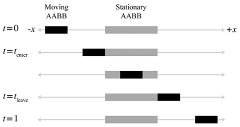
As we advance in time, the line segment representing the moving box will slide along the number
line. In the illustration in Figure A.15, at
where
Likewise, we can solve for
Three important points are noted here:
-
If the denominator
-
If the moving box begins on the right side of the stationary box
and moves left, then
-
The values for
We now have a way to find the interval of time, bounded by
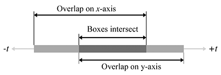
If the interval is empty, then the boxes never collide. If the interval lies completely outside
the range
Unfortunately, in practice, bounding boxes for objects are rarely axially aligned in the same coordinate space. However, because this test is relatively fast, it is useful as a preliminary trivial rejection test, to be followed by a more specific (and usually more expensive) test.
A.18Intersection of a Ray and an AABB
Computing the intersection of a ray with an AABB is an important calculation because the result of this test is commonly used for trivial rejection on more complicated objects. (For example, if we wish to raytrace against multiple triangle meshes, we can first raytrace against the AABBs of the meshes to trivially reject entire meshes at once, rather than having to check each triangle.)
Woo [7] describes a method that first determines which side of the box would be intersected and then performs a ray-plane intersection test against the plane containing that side. If the point of intersection with the plane is within the box, then there is an intersection; otherwise, there is no intersection. This is implemented in Listing A.6.
// Return parametric point of intersection 0...1, or a really huge
// number if no intersection is found
float AABB3::rayIntersect(
    const Vector3 &rayOrg,      // orgin of the ray
    const Vector3 &rayDelta,    // length and direction of the ray
    Vector3 *returnNormal       // optionally, the normal is returned
) const {

    // We'll return this huge number if no intersection
    const float kNoIntersection = FLT_MAX;

    // Check for point inside box, trivial reject, and
    // determine parametric distance to each front face
    bool inside = true;

    float xt, xn;
    if (rayOrg.x < min.x) {
        xt = min.x - rayOrg.x;
        if (xt > rayDelta.x) return kNoIntersection;
        xt /= rayDelta.x;
        inside = false;
        xn = -1.0f;
    } else if (rayOrg.x > max.x) {
        xt = max.x - rayOrg.x;
        if (xt < rayDelta.x) return kNoIntersection;
        xt /= rayDelta.x;
        inside = false;
        xn = 1.0f;
    } else {
        xt = -1.0f;
    }

    float yt, yn;
    if (rayOrg.y < min.y) {
        yt = min.y - rayOrg.y;
        if (yt > rayDelta.y) return kNoIntersection;
        yt /= rayDelta.y;
        inside = false;
        yn = -1.0f;
    } else if (rayOrg.y > max.y) {
        yt = max.y - rayOrg.y;
        if (yt < rayDelta.y) return kNoIntersection;
        yt /= rayDelta.y;
        inside = false;
        yn = 1.0f;
    } else {
        yt = -1.0f;
    }

    float zt, zn;
    if (rayOrg.z < min.z) {
        zt = min.z - rayOrg.z;
        if (zt > rayDelta.z) return kNoIntersection;
        zt /= rayDelta.z;
        inside = false;
        zn = -1.0f;
    } else if (rayOrg.z > max.z) {
        zt = max.z - rayOrg.z;
        if (zt < rayDelta.z) return kNoIntersection;
        zt /= rayDelta.z;
        inside = false;
        zn = 1.0f;
    } else {
        zt = -1.0f;
    }

    // Ray origin inside box?
    if (inside) {
        if (returnNormal != NULL) {
            *returnNormal = -rayDelta;
            returnNormal->normalize();
        }
        return 0.0f;
    }

    // Select farthest plane - this is
    // the plane of intersection.
    int which = 0;
    float t = xt;
    if (yt > t) {
        which = 1;
        t = yt;
    }
    if (zt > t) {
        which = 2;
        t = zt;
    }
    switch (which) {

        case 0: // intersect with yz plane
        {
            float y = rayOrg.y + rayDelta.y*t;
            if (y < min.y || y > max.y) return kNoIntersection;
            float z = rayOrg.z + rayDelta.z*t;
            if (z < min.z || z > max.z) return kNoIntersection;

            if (returnNormal != NULL) {
                returnNormal->x = xn;
                returnNormal->y = 0.0f;
                returnNormal->z = 0.0f;
            }

        } break;

        case 1: // intersect with xz plane
        {
            float x = rayOrg.x + rayDelta.x*t;
            if (x < min.x || x > max.x) return kNoIntersection;
            float z = rayOrg.z + rayDelta.z*t;
            if (z < min.z || z > max.z) return kNoIntersection;

            if (returnNormal != NULL) {
                returnNormal->x = 0.0f;
                returnNormal->y = yn;
                returnNormal->z = 0.0f;
            }

        } break;

        case 2: // intersect with xy plane
        {
            float x = rayOrg.x + rayDelta.x*t;
            if (x < min.x || x > max.x) return kNoIntersection;
            float y = rayOrg.y + rayDelta.y*t;
            if (y < min.y || y > max.y) return kNoIntersection;

            if (returnNormal != NULL) {
                returnNormal->x = 0.0f;
                returnNormal->y = 0.0f;
                returnNormal->z = zn;
            }

        } break;
    }

    // Return parametric point of intersection
    return t;

}
- This is one of Fletcher's favorite interview questions. It's surprising how many programmers do not know how to perform this very simple operation. Don't be one of those applicants!